Place Fabrication Parts in a Revit Model
Tweet
The fabrication part of the Revit software is doing a great job as it helps to bridge the divide among the detailers and designers. The fabrication part of the Revit software helps to allow the detailers to use their design models in the native format to route the fabrication-level content. The Revit fabrication also helps to enable the user to get the estimates of the fabrication level. There are numerous extensions in the Revit software which has been used for fabrication.
These extensions of the Revit software are easy to import as an MAJ file which can be used for the default templates of the users as well as help to set standards for the spooling in Fabrication. The design contractor or build contractor has the option to design in the native Revit content and after that, they can convert those designs to fabrication during the time of the construction process.
This process provides flexibility to the designers to work along with outside teams as well as they can convert their designs saving rework later. During the design conversion procedure, there is a time in which there not will be a fabrication part which replaces the Revit content accurately. In this context, a fabrication database is required which optimizes the environment and standards of the designs.

The use of the MEP fabrication parts palette is also known as the Parts browser. This Parts browser helps to select a service and a palette as well as helps to select the fabrication parts to the place within the drawing area. In the case that no parts have been included in the fabrication part palette, users can click on the settings option to open the fabrication setting dialog box. Through this process, users can load content into the MEP fabrication parts palette of the Revit software.
New fabrication features in the Revit software
There are numerous new fabrication features in the Revit software, which are as follows:
➢ Users are able to select “Straight” from the mechanical, electrical and plumbing (MEP) Fabrication Parts palette.
➢ Users can also select the required duct size in the Properties palette.
➢ A start point can be picked by the users in the Revit software. In addition, users can also pick again to straight another at the end of the previous start point.
➢ Users are able to choose “Transition” fitting from the Fab palette.
➢ Users can also change the “Secondary End” in the properties palette to the desired duct size.
➢ Users can also select to place the transition at the end of the run.
➢ Through the fabrication part of the Revit software, users can pick the place to the straight as well as they can also cancel the straight command.
➢ The duct segment can also be selected by the users through the fabrication parts of the Revit software.
The functionality of the fabrication parts of the Revit software
The Revit fabrication features have several functionalities, which are as follows:
The maintenance of the Revit style of modelling
The modelling procedure for the standard Revit MEP elements strongly depends upon the straights which helps to allow the system family settings to insert transitions and bends into their designs.
The new fabrication features in the Revit software have been required for picking and placing all the components into designs.
Supports engineering designs
The primary features of the fabrication parts in Revit software help to support the design procedures. The default fabrication configuration does not have any air terminals, but this feature allows the users to the airflow calculations along with the Revit spaces which supports the engineering design processes.
Spool drawings
The spool drawing helps to make the connection between the building scale shop drawing of the contractors and the purchased part fabrication cut and bend drawings. This helps to represent a handful of parts which are going to be assembled in the shop.
Supporting robotic field point layout
The use of the robotic field layout tool is effective in translating the BIM-coordinated layout into the actual location in the building. To accomplish this procedure in the Revit software, users can add a nested “point” family in the hanger families.
The fabrication parts of the Revit software are not part of the Revit family. There are more manual methods to identify and export hanger locations that will have to be devised.
To get online demonstration, watch the following video tutorial.
Video Source: Dzan Ta
Design model creation
There is no fabrication configuration editor in the case of the requirement of minor modifications, though there is a family editor which is the most useful thing in the Revit software. Users have to buy CADmep or CAMduct before adding the insulation to their design model.

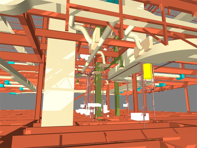
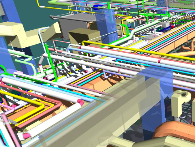
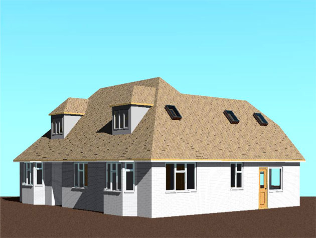
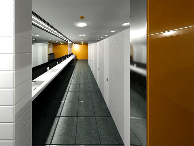
Gallery
Feel free to contact us for BIM requirements. One of our representative will respond you within 24 Hours. Send us your projects requirement today and grow your project.
Explore More !