Revit 2023: Beginner Tips for Creating a Floor Plan
Tweet
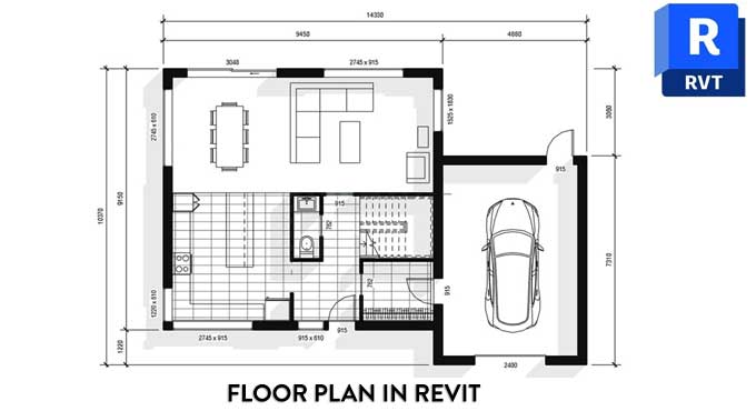
Creating 3D models is the most common use of Revit. A floor plan can be quickly created by drafting a layout. You need to follow certain steps in order to create an easy and nice floor plan using Revit.
Setting up a proper level height
If you do not need elevations or 3D views at the time, you should still assign the walls to specific levels even if you do not require elevations or 3D views at that time.
Make sure that all of the required levels have been created by going to the elevation view. Ensure that they are set to the correct height, but if necessary, you can adjust them later.
Intersect walls from internal to external
It is still a good idea to place one of the corners of the building at the intersection of the internal origin of your project, regardless of your lack of concern about the coordinate system. Depending on the version of Revit that you are using, the internal origin in Revit 2020 and later is indicated by an arrow symbol.
A project origin point should not be confused with a project base point or a survey point. While all of these points should be in the same position at the start of the project, there is a difference between them. As the origin for CAD exports, this point will be used. In the same way, CAD files or other formats can be linked.
Visibility or Graphics can be accessed by the shortcut VG. To access the site submenu, scroll below. Verify the Internal Origin checkbox. Your plan view should display the arrow icon.
Add detail lines to the layout
The problem with Revit is that there is no real way to create a quick layout in the same way that a quick layout can be created in AutoCAD. You are not quite right, the only thing you need to do is use the appropriate tools in order to do it.
A layout can be created directly using walls, or it can also be created using detail lines. DL is the shortcut you need to use. A single view shows these lines, but they are not included in the 3D model. Coloured lines should be used to distinguish model elements from each other.
Having created a draft layout, you have a variety of options to match your walls and other elements to the details in the layout. It would probably be best if you used the Align tool or the AL shortcut to align the objects. In order to edit a wall, type AL, click the reference line for the detail line, and then click the edge of the wall. There will be a movement of the wall so that it aligns with the detail line.
To create similar work, use shortcut cs
You can create a similar element by selecting an element and using the shortcut CS. There is no doubt that this is one of the best ways to be efficient. Using this tool, we are able to quickly create walls as shown in the example below.
Consider using temporary dimensions
When you select an element, a blue dimension will appear. This is referred to as a temporary dimension. You can adjust the witness lines by dragging the dots on the witness lines. If you wish to adjust the dimension, you will need to change the value of the blue text. It is possible to make a dimension permanent in the view by clicking on the dimension symbol.
Adjust the walls by using Trim
The TRIM tool is well known to former AutoCAD users, or you might be familiar with its shortcut: TR tool. This tool can be used to join elements together by trimming or extending them. It is also possible to extend elements using the same TRIM tool. A layout can be completed by using detail lines, alignment, temporary dimensions, and trimming.
Adjust Family types after adding Doors and Windows
You can begin adding doors and windows once your wall layout is complete. Time can be saved by using shortcuts:
Some of those shortcuts are as follows:
DR - Door
WN - Windows
Spacebar - Flip Door, windows and wall orientation
WA - Walls
The process of creating and controlling doors is simple. By pressing the Spacebar or clicking the arrow symbol, you can flip the doors or windows.
The next step is to add windows. Make sure the side is properly positioned on the wall by clicking on it. Make sure to flip the arrow symbol on the exterior of the window if necessary.
To get online demonstration, watch the following video tutorial.
Video Source: Revit Pure
Add lines and components
Many people might have trouble with this part. The search for good Revit components isn't as easy as it seems. The template contains components that need to be added. By using the Create Similar tool or the shortcut CS or by copying/pasting.
The Drawing must be Annotated
Tags for windows and doors are included in the template. In the case of door tags, the width is indicated, while the size of the window tag is indicated by the width x height. Intelligent tags automatically adjust if the door width changes. A vertical or horizontal tag can be selected in the options bar.
Make sure all doors and windows are tagged. It is possible to add dimensions too, or you can use the shortcut: DI.
Place the items and designs on the sheets and then print
The view should be placed on a sheet after the final touches are made. The crop region around the house should be adjusted. Make adjustments to the sheet's information. When everything is finished you are ready to print your floor plan.
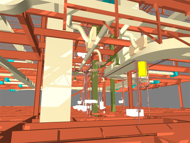
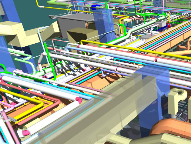
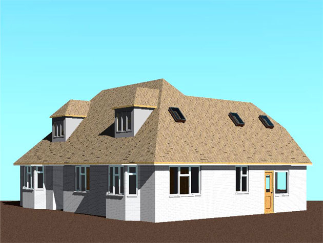
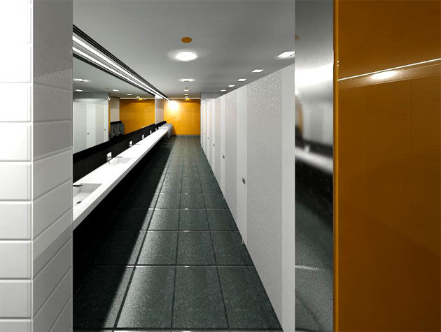
Gallery
Feel free to contact us for BIM requirements. One of our representative will respond you within 24 Hours. Send us your projects requirement today and grow your project.
Explore More !