Truss Design Using Adaptive Component In Revit
Tweet
Versatile parts are utilized for receiving a family to different situations by observing the parametric standards. There is an essential distinction between the standard segments and the versatile segments. In normal parts, the calculation of the family is identified with one extraordinary addition point and in versatile segments, the math can be identified with the different inclusion points. Clients can make dynamic versatile segments in Revit by utilizing versatile segments.
Production of adaptive components
- There are two kinds of family layouts to make the adaptive components.
- Metric Generic Model Adaptive
- Metric Generic Model Pattern Based
Use of adaptive components
1. It very well may be utilized in
2. Design board families,
3. Versatile segment families,
4. Theoretical massing climate and
4. Different ventures.
Benefits
- Clients can have numerous types of a family without the requirement for various boundary esteems.
- It is extremely compelling on complex blind dividers.
- It is utilized in facade panelization.
- Versatile Components are utilized for railings, mechanical and electrical installations.
Place structural truss elements in your model
Truss layouts transform to fit the full span of the truss, creating framing elements that correspond to the lines in the transformed truss layout.
- Open a view of the building level where you want to add the truss.
- Click Structure tab structure panel (Truss).
- On the Properties palette, from the Type Selector drop-down, select the truss type.
- Click Modify | Place Truss tabDraw panel (Line) to specify the start point and endpoint for the truss, or click (Pick Lines), and then select an edge or line to which users want to constrain the truss model.
All types within a truss family share the same profile layout. Individual types specify other parameters, such as the structural framing families used for modeling chords and web members. When you sketch a truss line, structural framing elements are created, placed on the layout lines specified for the selected family.
When you move the cursor over a truss in the drawing area, the truss element displays a set of dashed blue lines. Clicking any of these dashed blue lines selects the truss element itself. The sub-elements that comprise the truss, such as the top chord, bottom chord, and web members, are individually selectable.
Structural framing elements are created along each of these layout lines. You can select and define the structural framing elements in the truss layout family. Several different types of the same family can have different pre-set framing families using the same geometric layout.
The visibility and Graphics of a truss element are controlled by the framing members making up the truss element. Structural members associated with the truss type are included in the geometric layout. These structural members can be changed to a different size, but they must be selected from sizes available within the specific truss family.
Create a custom truss to place within a structural model
A truss layout family consists of lines that define truss elements such as chords and webs. Chord and web members are created such that their center lines (local x-axis) will lie along the layout lines that you define in the truss layout family. The entire layout will be transformed such that the distance between the 2 end reference planes will be determined by the truss instance based on its shape in the project.
Click File tab New Family. Navigate to the Imperial or Metric template directory and select the Structural Trusses. rft family template file. Click the Open button to open a new family file.
The structural truss family template provides 5 permanent reference planes: top, bottom, left, center, and right; the left and right planes indicate the span length of the truss. Truss layout lines that end at these planes or are coincident with them will maintain this relationship during layout transformation in the project environment.
- Click Create tab detail panel.
- Sketch along the top reference plane to define the top chord.
- Click the lock symbol attached to the line to lock the chord to the plane.
- Click Create tab detail panel (Bottom Chord).
- Sketch along the bottom reference plane to define the bottom chord.
- Again, click the lock symbol to lock the chord to the plane.
- Click Create tab detail panel (Web).
- Sketch the panel webs.
If needed, place additional dimensions between sketched lines and reference planes.
The Length parameter may be used in your truss layout family to perform calculations to specify the exact location of vertical web members or to calculate the number of panels to create in the project environment.
Click Insert tabLoad from Library panel (Load Framing Family).
In order to specify structural framing families for the truss layout family to use, you must load them in your truss layout family. Navigate to the Imperial or Metric family directory and select the structural framing families for chords and webs. These must be structural framing families or generic annotation families. Repeat this step to specify for each planned type of truss.
- Click Create tab properties panel (Family Types). In the Family Types dialog, click New and provide a name for this truss type. Repeat this step for each planned type of this truss family.
- For each truss family type, select the desired framing type for top chord, bottom chord, vertical webs, and diagonal webs. Click OK to close the dialog.
- Click File tab Save As. Navigate to your family directory, provide a name for the new truss family, and click Save.
- To load into an open project, click Create tabFamily Editor panel (Load into Project).
To get more details, go through the following video tutorial www.youtube.com
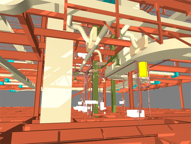
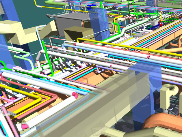
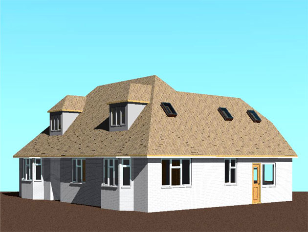
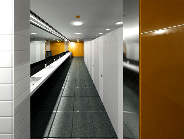
Gallery
Feel free to contact us for BIM requirements. One of our representative will respond you within 24 Hours. Send us your projects requirement today and grow your project.
Explore More !